
| Home | All's well until you get bumps and rises and falls and turns. |
|
|
|
THE PROBLEM
Ever driven the Oval on a pre-v0.4.6 Racer version? You probably couldn't get far without severely sliding off. The problem is that the polygons of the track are too choppy to drive on just like that. Driving from one to the other polygon just gives too much differences in grade and banking. Even in v0.4.7, splines didn't work too good on Ovals. In v0.4.8, the method is extended to use a full 3D surface patch.
THE FIRST THOUGHT
Why not create more polygons then? First, this would make rendering slower. I'd rather have hardware support for patches before this is really a valid option. Ok, so Quake3 does something like this, but we just want to drive our beloved available tracks. Second, this makes tire intersections with the surface slower, since there are more polygons to check. Third, it won't solve the problem; tracks ARE smoother than the best of polygon representations can give you.
A SOLUTION
A possible solution is to use splines. However, spline surfaces, NURBS surfaces and all, they're slow right? No they're not, if we're using your brain and come up with a fast solution. I'll present you the basics of what Racer uses.
In addition to the normal soup of polygons that Racer drives on, there are certain optimizations, like keeping a flag for every object whether it's drivable or not. On top of that, you can (and should) define a patch that matches the road (and possibly the surrounding grass, work is still in progress and experience is little).
WHAT WE HAVE FOR RE-USE
As Racer normally drove right on the polygons, a ray-triangle intersection was used, from Tomas Moeller, and this works quite fast & elegantly. In fact, it is still used when the car drives off the spline patch, as a catch-all (unless you use some kind of Lidar high-density data, but that only came much later). It is used again with the spline surface in determining where you are on the patch. In TrackEd, you recreate a web of triangles which directly maps onto the polygons of the 3D models. While driving, instead of checking the 3D models, now, Racer checks the overlaying spline triangles first. If a hit is found, the algorithm used returns U and V coordinates, which, just like in texturemapping, 3D programs and such, are the barycentric coordinates.
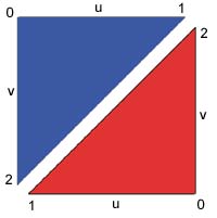 |
Here you see the two triangles that are created when you create at least 2 spline cross-sections. Notice the vertex numbering; this is important for the 'u' and 'v' coordinates to be correctly placed. Note the resulting clockwise ordering (hey, I might just reverse that because of culling; in fact, I did this in v0.4.7). |
THE WAY IT WORKS
In TrackEd, you can define lateral lines as spline lines. Between every 2 lines, a quad (implemented by a pair of triangles) is created. You just lay down all the lines in TrackEd and the end result will be a polygon patch. Through each vertex, at each side of the road, a 3D spline is drawn (actually there are 3 splines per side, for the X, Y and Z coordinates; this makes for 6 long splines in total, given 2 traces through the track at the extreme left and extreme right side of the track). In the future, more splines may be drawn to give more accurate bumps somewhere in the middle of the track. You can see the spline triangles in TrackEd by selecting Spline Mode. Racer v0.4.7 used a 1-dimensional spline, for Y only. But this didn't work for ovals: consider a full circular oval track; this may very well have Y coordinates at all the same height. Obviously the spline will stay at the same height. I had to extend the system and run 3 splines through X, Y and Z coordinates.
Now when you drive somewhere on the patch, a ray-triangle hit is found into one the the spline triangles (displayed in green in TrackEd). From the resulting U/V coordinates, we can estimate where the smoothed surface patch is; just feed the UV coordinates into the splines, and you get point P. This point may be a little off with respect to the original ray-triangle intersection point. Gregor Veble came up with a method to iterate a few times and get a better estimated point P at every iteration. However, v0.4.8 just uses P as it is generated by the splines. For now, it seems to be close enough, and I'll avoid the extra calculations.
As for the P calculations; the u and v show you how far the car is on the triangle laterally (u) and longitudinally (v). So you calculate the spline results at 'v' (x=splineX->GetValueAt(v), y=..., z=...) and interpolate (linearly) like:
x = x0 + u*(x1-x0)
y = y0 + u*(y1-y0)
z = z0 + u*(z1-z0)
where x0 is the X-value on the left side of the road, and x1 the X-value on the right side of the road. This linear interpolation may be refined when you put in multiple traces.
Some tricky bits appear as the two triangles are eachother's opposite, so we have to flip the u/v coordinates for every 2nd triangle (a simple triNumber&1 check). Also, the triangle should be as square as possible to avoid distortion of the coordinates (see below). Although this will be hard to feel for the driver, you can imagine the effect of being like trying to put a quad texture onto the 2 triangles. This also leads to distortion when you shear the triangles at the shared edge.
THE PROS
Using the spline patch is actually faster than directly checking for the 3D model polygons themselves, since there are fewer spline polygons. Still, an area subdivision method is needed to quickly rule out spline triangles, like a quadtree, especially for larger tracks. An AABB tree, not exactly the same as a quadtree, is used from Racer v0.4.9 on. This tree splits a single dimension at each node, progressively refining the track until a single triangle remains (in the leaf nodes). They are actually generating when you load the track, since it turned out that the creation did not take that much time (in the order of 1 second on a PII-400).
THE CONS
The disadvantages of spline triangles? It costs a little more in evaluating the spline function, which is a cubic function (Hermite currently, more specifically Non-Uniform Hermite, but others may be used). Other than that, it has too many advantages, most not even discovered by me, to go unused. Note that Racer spaces out the knots using sqrt(distance) between the knots, to get a more even weighed spline (to avoid sparsely spaced sections of splines that lie next to densely spaced section of splines to give continuity problems).
USING QUADS INSTEAD OF TRIANGLES
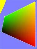
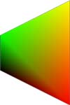 |
Alas, the triangles seem to give a bit of trouble
in banked curves. To the left you can see the problem (the screenshot is
from an application that raytraces into the triangles and visualizes the
resulting u and v coordinates using color). There's a noticable change in
the 'v' coordinate (notice green is the 'v' coordinate, red is 'u', so yellow
is where u=v=1) when the triangles get out of shape (this would be a mildly
exaggerated quad from a tight curve). This is already noticable it seems
at the Oval, and the problem gets worse when also shearing the quad (pushing
the greenest vertex to the left for example). A better quad method can be
found to get better U/V coordinate spacing. In turns, one of the 2 triangles
gets thinner, especially in tight turns with few triangles, which makes
for differently varying U and V coordinates. You can clearly see the quite
big difference in the size of the two triangles in the image to the left. An idea for this is perspective-correct texturemapping, for which Magic Software has some documents, but I haven't investigated into this in terms of actual code. |
A formula for ray-quad intersection was found by Gregor Veble. Using this formula on quads (instead of 2 triangles) gives much better results; the U and V coordinates now vary smoothly over the entire quad (plus that at the corner points U/V are exactly 0 or 1). The formula is quite big and I'll add it later. Note that there are problems with this (adressed in Racer v0.9.0RC6); the triangle UV coordinates (during ray-surface detection) were superseeded by quad UV's, but if the initial triangle hit would *just* miss the quad, the original triangle UV coordinates were used and resulted in a slight surface height mismatch. Besides, the quad intersection routine was basically 2D, resulting in slighty-off situations when cambering a lot. v0.9.0RC6+ adresses this by tesselating the spline laterally to make the sections more planar. Imagine an oval straight section turning into a corner; the quads there become highly non-planar, and triangulation with just 2 triangles per spline section results in very bad alignment (the triangles have different normals, sensable if you're inside a stiff car). Lateral tesselation helps a LOT to overcome this. An alternative to the big formula described above is to look at the book 'Graphics Gems V' in chapter 5.2 (quad_gg.c). The algorithm is described in "Ray Intersection of Tessellated Surfaces". The source code for the books can be found here. You can find more info on the Graphics Gems series here. |
 |
OTHER USES OF THE U AND V COORDINATES
The U and V coordinates are interesting, since they tell you where you are on the track. Every triangle knows how far it's up the track, so you can directly derive the longitudinal position of the car as v+longitudinal_start_of_triangle. This can quickly tell you the relative positions of the cars. Also, the lateral, 'u' value gives you an idea of how far you are from the left & right side, giving important information for the AI, most probably.
OTHER IDEAS
This text only presents a left-right interpolation technique.
Ofcourse, multiple traces would be possible laterally. GPL (Grand Prix Legends) often uses about 14, for
example. It might be needed anyway, if only for the bump at Monaco. :)
(last updated December 30, 2014 )