
| Home | Pacejka's Magic Formula is used for expressing tire forces. |
|
|
|
What is Pacejka's Magic Formula?
Pacejka curves are a big part of the tire models (and tire modeling is about 50% of a car simulator). They represent the forces that are generated by the tire as a result of the tire not following the road precisely. Steer the tire a little, and you get a slip angle, and this is input into the Pacejka Fy formula, giving a sideways force. Press the throttle, and the wheel starts spinning a bit; this gives a different ratio of wheel spin speed vs. ground speed, and this gives a forward (longitudinal) force.
Pacejka's Magic Formula is a standard in a lot of today's racing simulations applications (not necessarily games; it's mostly professional applications that use it). Multiple versions exist - Racer mostly uses a 1989 version of Pacejka it seems; the formula was originally taken from Giancarlo Genta's book 'Motor Vehicle Dynamics', which is from 1997. The book also contains a few Pacejka example sets, not all too accurate but useful nevertheless.
The default Pacejka formula in Racer uses coefficients a<n> for lateral forces, b<n> for longitudinal and c<n> for aligning moment (force feedback/Mz). Racer will soon support MF5.2, which stands for Magic Formula 5.2, which is used more often these days. Although newer, the real crux is to get tire data, which is scarce and heavily protected intellectual property just about all the time. However, sometimes you may get your hands on approximate data, which just hides subtleties which are not too important anyway.
MF 5.2 uses newly named variables, such as PCx1, PDy1 etc. These are the base fitting coefficients to get the mathematical curves to match the empirical (measured) tire data. Then, lambda values are used in various places to be able to tweak the tire in more real-life terms.
The text below focuses on the default model, Pacejka89. Note that the text speaks of '96', which I though the version was until recently. The future may see more use of MF5.2 Pacejka sets, since that is what I've seen in the field more often the last couple of years.
The curves output tire forces (lateral/longitudinal) and moments (Mz for aligning moment for example) based on just a few inputs. These inputs are:
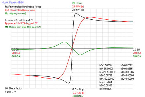
Pacejka curves typically look like this. the black line indicates Fx (longitudinal, a result from slip ratio), the red is Fy (lateral) and the green line is Mz (aligning moment, or what you feel as force feedback).
The values are often measured and then fit using tools such as MF-Tyre from TU Delft. Since these measurements use real tires, high input values are difficult to measure; the tires are destroyed or modified too quickly to be measurable. Therefore, most curves are really limited in their inputs. Racer v0.8.34+ supports limiting the inputs using these values in car.ini:
The defaults for these values are in data/cars/default/car.ini and normally don't limit the input values, but can be tweaked for specific cars to tune oversteer/understeer.
Magic Formula 5.2 usage
Currently implemented fully in (v0.8.8), the MF5.2 set can be activated by setting 'model=1' in your car.ini pacejka data. The usual solution though is to use an external TIR file (see below), but you can also specify coefficients inside a car.ini directly. An example extract:
pacejka_mf52
{
  ; Pacejka89 (0) or MF5.2 (1)?
  model=1
  pcx1=1.3
  pdx1=1.2
  pkx1=30
  ; Lateral
  pcy1=1.34
  pdy1=1.04
  pky1=-25.0
  pky2=2.71
  pky3=0.39
}

wheel0
{
...
  pacejka~pacejka_mf52
  {
  }

}
Importing TIR files
If you have some industry standard .tir files (MFTyre for example), you can skip all the copying & pasting of all the coefficients and directly import the TIR file itself:
pacejka_mf52
{
  ; Pacejka89 (0) or MF5.2 (1)?
  model=1
  ; TIR file
  import_file=my_custom_tire.tir
}

wheel0
{
...
  pacejka~pacejka_mf52
  {
  }

}
Currently only MF5.2 TIR files will work (v0.9). Note that MF 6.1 is mostly the same as MF 5.2, so these might work as well (except for the pressure coefficients not working).
Negating camber (v0.9.0RC5+)
When encountering TIR files in the wild, it seems the axis systems vary quite a bit. For every magic formula version out there, there seem to be variations that flip camber sign for example, or entire axes. An example can be the subtle inversion of camber forces; here, the forces are offset the wrong way when camber is fed into the formula. Racer will do a bit of checking and give warnings in the QLOG file if the Fy curve for example seems to move the wrong way when camber is applied. It can be quite an ordeal if you use bad axis systems by mistake; the tire appears to work but isn't quite right. What makes it worse is that for example in the book 'Tyre and Vehicle Dynamics' from Pacejka himself, there are 4 variations on the axes; SAE, adapted SAE (used in the book), ISO and adapted ISO.
A quick fix that avoids messing with the coefficients themselves is to reverse camber in the calculations inside the Pacejka source code. This can be done with the setting wheel<n>.pacejka.negate_camber. Defaulting to 0, it does nothing. If set to 1, it will internally use the negated camber as an input to the Pacejka formulae.
When obtaining TIR files, it is always good to verify them by sight in Racer's Pacejka player (pacejka.exe).
MF 5.2 source code
The source code from the Racer v0.8.9 version:
void RPacejka::CalcMF52()
// Pacejka MF5.2 (~2006)
{
   rfloat Fx0,Dx,Cx,Ex,Bx,dfz,Fz0,Fz0_der;             // Nominal load, adapted nominal load
   rfloat kx,k,mux,sign_kx;
   rfloat Shx,Svx,Kx,gamma,gamma_x;
   rfloat Fzn;                     // Fz in Newtons
   rfloat tmp;

   //
   // Global
   //
   k=slipPercentage*0.01f;   // Slip ratio
   Fzn=Fz*1000.0f;
   Fz0=fz0; //4500;
   Fz0_der=lfz0*Fz0;
   dfz=(Fzn-Fz0_der)/Fz0_der;
   gamma=camber/RR_RAD2DEG;
   //
   // Fx (pure slip)
   //
   Shx=(phx1+phx2*dfz)*lhx;
   Svx=Fzn*(pvx1+pvx2*dfz)*lvx*lmux;
   kx=k+Shx;
   if(kx<0)sign_kx=-1.0f;
   else    sign_kx=1.0f;

   gamma_x=gamma*lgax;

   Cx=pcx1*lcx;
   mux=(pdx1+pdx2*dfz)*(1.0f-pdx3*gamma_x*gamma_x)*lmux;     // Different in Pac2006
   Ex=(pex1+pex2*dfz+pex3*dfz*dfz)*(1.0f-pex4*sign_kx)*lex;
   // Limiter on Ex (eq 23)
   if(Ex>1.0f)Ex=1.0f;
   Dx=mux*Fzn;
   Kx=Fzn*(pkx1+pkx2*dfz)*expf(pkx3*dfz)*lkx;                // K=BCD (=stiffness in percent)
   // Low velocity trouble
   tmp=Cx*Dx;
   if(fabs(tmp)<0.001f)
   Bx=Kx/(tmp+0.001f);
   else
   Bx=Kx/tmp;

   tmp=Bx*kx;
   Fx0=Dx*sinf(Cx*atanf(tmp-Ex*(tmp-atanf(tmp))))+Svx;

   //
   // Fy
   //
   rfloat Fy0,Dy,Cy,Ey,By;
   rfloat localMuy;
   rfloat Shy,Svy,Ky;
   rfloat say,sign_alpha_y;
   rfloat gamma_y;
   rfloat alpha;

   alpha=sideSlip/RR_RAD2DEG;
   gamma_y=gamma*lgay;

   Cy=pcy1*lcy;
   localMuy=(pdy1+pdy2*dfz)*(1.0f-pdy3*gamma_y*gamma_y)*lmuy;
   Dy=localMuy*Fzn;
   Ky=pky1*Fz0_der*sinf(2.0f*atanf(Fzn/(pky2*Fz0_der)))*(1.0f-pky3*fabs(gamma_y))*lfz0*lky;    // =BCD=stiffness at slipangle 0

   tmp=Cy*Dy;
   if(fabs(tmp)<0.001f)
     By=Ky/(tmp+0.001f);
   else
     By=Ky/tmp;

   Shy=(phy1+phy2*dfz)*lhy+phy3*gamma_y;
   Svy=Fzn*((pvy1+pvy2*dfz)*lvy+(pvy3+pvy4*dfz)*gamma_y)*lmuy;
   say=alpha+Shy;

   if(say<0)sign_alpha_y=-1.0f;
   else     sign_alpha_y=1.0f;
   Ey=(pey1+pey2*dfz)*(1.0f-(pey3+pey4*gamma_y)*sign_alpha_y)*ley;
   // Limiter on Ey (eq 35)
   if(Ey>1.0f)Ey=1.0f;

   // Lateral base force
   tmp=By*say;
   Fy0=Dy*sinf(Cy*atanf(tmp-Ey*(tmp-atan(tmp))))+Svy;

   //
   // Mz
   //
   rfloat Mzr;
   rfloat t0,Dt,Ct,Bt,alpha_t,Et,gamma_z;
   rfloat Sht,Shf;
   rfloat Br,R0;
   rfloat alpha_r,Dr;
   const float lr=1.0f;        // Not found in paper at lambda section

   R0=r0;
   gamma_z=gamma*lgaz;

   Sht=qhz1+qhz2*dfz+(qhz3+qhz4*dfz)*gamma_z;
   alpha_t=alpha+Sht;

   // Avoid division by zero
   if(fabs(Ky)<0.001f)
   if(Ky<0)Ky=-0.001f;
   else    Ky=0.001f;

   Shf=Shy+Svy/Ky;
   alpha_r=alpha+Shf;
   Bt=(qbz1+qbz2*dfz+qbz3*dfz*dfz)*(1.0f+qbz4*gamma_z+qbz5*fabs(gamma_y))*lky/lmuy;    // Pac2006 adds gamma_y^2 dependence (qbz6)
   Ct=qcz1;
   Dt=Fzn*(qdz1+qdz2*dfz)*(1.0f+qdz3*gamma_z+qdz4*gamma_z*gamma_z)*(R0/Fz0_der)*lt;        // lt=lamba_t?

   Et=(qez1+qez2*dfz+qez3*dfz*dfz)*(1.0f+(qez4+qez5*gamma_z)*(2.0f/3.14159265f)*atanf(Bt*Ct*alpha_t));   // <=1
   // Clamp Et (eq 51)
   if(Et>1.0f)Et=1.0f;

   Br=qbz9*lky/lmuy+qbz10*By*Cy;      // Preferred qbz9=0
   tmp=Bt*alpha_t;
   t0=Dt*cosf(Ct*atanf(tmp-Et*(tmp-atan(tmp))))*cosf(alpha);           // t_alpha_t in the paper
   Dr=Fzn*((qdz6+qdz7*dfz)*lr+(qdz8+qdz9*dfz)*gamma_z)*R0*lmuy;        // *cosf(alpha_t) for Pac2006 (in MF52 this is still in Mzr=... below)
   Mzr=Dr*cosf(Ct*atanf(Br*alpha_r))*cos(alpha);                       // last cos(alpha) is cos(alpha_t) in Pac2006

   // No combined aligning moment
   Mz=-t0*Fy0+Mzr;

   //
   // Combined slip
   //
   // Combine (page 30+)
   // Longitudinal
   float Shxa,Exa,Cxa,Bxa,alpha_s,Gxa0,Gxa;
   Shxa=rhx1;
   Exa=rex1+rex2*dfz;
   Cxa=rcx1;
   Bxa=rbx1*cosf(atan(rbx2*k))*lxal;   // +rbx3*gammaStar*gammaStar) (Pac2006)
   alpha_s=alpha+Shxa;
   Gxa0=cos(Cxa*atan(Bxa*Shxa-Exa*(Bxa*Shxa-atan(Bxa*Shxa))));
   if(fabs(Gxa0)>D3_EPSILON)
   Gxa=cos(Cxa*atan(Bxa*alpha_s-Exa*(Bxa*alpha_s-atan(Bxa*alpha_s))))/Gxa0;
   else
   Gxa=0;        // Or 1 for super grip?
   Fx=Gxa*Fx0;

   // Lateral
   float Dvyk,Svyk,Shyk,Eyk,Cyk,Byk,ks,Gyk0,Gyk;

   Dvyk=muy*Fz*(rvy1+rvy2*dfz+rvy3*gamma)*cosf(atanf(rvy4*alpha));
   Svyk=Dvyk*sin(rvy5*atan(rvy6*k))*lvyka;
   Shyk=rhy1+rhy2*dfz;
   Eyk=rey1+rey2*dfz;
   Cyk=rcy1;
   Byk=rby1*cosf(atanf(rby2*(alpha-rby3)))*lyka;
   ks=k+Shyk;
   Gyk0=cosf(Cyk*atanf(Byk*Shyk-Eyk*(Byk*Shyk-atanf(Byk*Shyk))));
   Gyk=cosf(Cyk*atanf(Byk*ks-Eyk*(Byk*ks-atanf(Byk*ks))))/Gyk0;

   Fy=Gyk*Fy0+Svyk;

   // Aligning torque
   float alpha_r_eq,alpha_t_eq,Mzr,Fy_der;
   float sign_alpha_t,sign_alpha_r;
   float kk,s,t;

   if(alpha_t>=0)sign_alpha_t=1.0f;
   else          sign_alpha_t=-1.0f;
   if(alpha_r>=0)sign_alpha_r=1.0f;
   else          sign_alpha_r=-1.0f;
   kk=Kx/Ky;
   kk=(kk*kk*k*k);     // kk^2*k^2
   alpha_r_eq=sqrtf(alpha_r*alpha_r+kk)*sign_alpha_r;
   alpha_t_eq=sqrtf(alpha_t*alpha_t+kk)*sign_alpha_t;
   s=(ssz1+ssz2*(Fy/Fz0_der)+(ssz3+ssz4*dfz)*gamma)*R0*ls;
   Mzr=Dr*cosf(atanf(Br*alpha_r_eq))*cosf(alpha);
   Fy_der=Fy-Svyk;
   // New pneumatic trail
   tmp=Bt*alpha_t_eq;
   t=Dt*cosf(Ct*atanf(tmp-Et*(tmp-atanf(tmp))))*cosf(alpha);

   // Add all aligning forces
   Mz=-t*Fy_der+Mzr+s*Fx;

   // Postprocess; negate for Racer?!
   Fy=-Fy;
   Mz=-Mz;

   // Static results
   latStiffness=-By*Cy*Dy;     // There's that '-' again for lateral force (Fy)
   longStiffness=Bx*Cx*Dx;     // In percent; for some uses multiply by 100 (!)
}
Pacejka Magic Formula 6.1
This enhanced set of formulae includes pressure effects. It is not yet implemented into Racer (v0.8.28 as I write this).
WHAT DO THE CURVES LOOK LIKE?
| Here you can see a typical bunch of Pacejka curves for longitudinal (forward) force (Fx), lateral (sideways) force (Fy) and aligning moment (Mz, which you feel at the steering wheel, the force-feedback for consumer FF wheels). Horizontally you see the inputs, as used for the 3 different curves. Vertically you see resulting forces (Fx/Fy) and torque (Mz). SR means slip ratio, and is defined as wheelSpinVelocity/groundVelocity-1. SA means slip angle and is the angle (in degrees) between the wheel heading and the wheel's actual velocity. Last, SA for Mz is the slip angle as used for the aligning moment (Mz). Note that Mz even crosses the horizontal line, which means that once you steer TOO MUCH, you even get negative feedback, making your wheel want to turn even MORE. Take a look at the black Fx curve: Fx peaks and then lowers back down again; this curve is a bit exaggerated perhaps; it should go down to about 75% peak force perhaps. Looking at the lateral curve, you can say that Fy peaks at about 4 degrees. This also is a bit rough; you would normally be more in the 6-15 degree range for your peak.
|
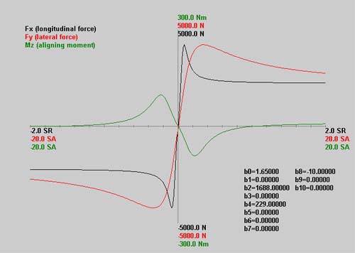 |
| Another example of a Pacejka curve from a different program is this curve, as used in EA's F1-2002 (data from the tire.tbc file). Used as a base tire curve, this is tweaked according to the situation (tire temperature for example). Notice that it stays at the peak very long and only gradually drops down: this tire is very forgiving. |
 |
SO WHAT DOES THE CURVE DO PHYSICS-WISE?
Longitudinal Pacejka (Fx) for example gives the amount of force that the tire generates. That is the force that moves the body forwards.
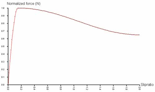
Input (horizontally) is slip ratio (SR); this is the ratio of wheel velocity vs. ground velocity. So if the wheel spins at twice the velocity of the ground, you get: SR=wheelVel/groundVel-1 (the -1 is there to make 0 the null situation) => SR=1. So if the wheel spins faster than the ground below, you get a forward force.
However, as you can see in the curve, you have a peak. Once your tire is really spinning a lot faster than the ground, you actually LOSE grip, which is why the graph drops again. The coefficients are just there to tweak the curve. High peak = high possible force, high line after the peak = still a lot of grip once you get a lot of wheelspin. Notice that because the curve dives down again, it's also harder to regain grip, since not much force is generated by the tire to reduce the spin back to normal again.
With lateral Pacejka it's the same idea, only based on slip angle (wheel direction vs. ground direction). The peak location is important here: F1 tires may peak around 6 degrees (displayed horizontally), road cars at perhaps 10-15 degrees. Again, if the graph drops too much after the peak, steering too much will cause more severe understeer effects. If the peak force slip angle is low (6 degrees) you'll have a fast reacting tire. If it's higher (some say Grand Prix Legend's peak slipangles are artificially high) you get smoother steering.
A big chunk in tire modelling is the way longitudinal and lateral forces are generated. Another big chunk is how they are combined, since (if you've heard of the friction circle) a tire cannot generate more than some maximum force, and this has to be split for lateral and longitudinal directions. So in other words, a maximum accelerating car couldn't keep this up while turning.
An editor for the Pacejka curves in Racer is part of the package and there is documentation for the Pacejka Player too.
Racer uses the Pacejka Magic Formula model for the tire forces.
Pros:
Cons:
Still, the Genta book contains 5 sets on which to build. But that means you have to understand a little of them. Unfortunately, the data is a bit lacking; some coefficients (for load sensitivity) are missing here & there. Still, it's good that they're there.
Longitudinal forces
The Pacejka96 formula calculates Fx (X is the SAE axis for the forward vehicle axis) as follows (in pseudo-code style, the actual formula is normally shown a little cleaner). The static input is the b<n> coefficients, and the dynamic input is load (Fz) and slipRatio (slipPercentage). Don't know where camber has gone. ;-)
The official Pacejka-96 longitudinal formula goes like this:
y(x) = D sin[ C arctan { Bx - E ( Bx - arctan(Bx))}]
where Y(X) = y(x) + Sv, and x = X + Sh.
The resulting force, Fx, is equal to Y(X). Actually, the same formulation is used for Fy and Mz (lateral force and aligning moment), only with different variations of calculating the BCDE variables. Y here represents output (Fx/Fy/Mz), X represents the input (slip ratio, slip angle).
A lot of things can be said on these variables. The basics are:
The B, C, D and E variables are functions of the wheel load, slip angle, slip ratio and camber. The influence of these inputs are given by the b0-b10 constants. Calculating these goes as follows (in pseudo-code format):
Here, Fz is the normal force, the load in English. The result is Fx, the longitudinal force. The input for Racer is the b0-b10 coefficients, which define the curve's peak and flow. Some interpretations for the Pacejka formula are:
There are 10 coefficients, b0-b10. With help of Brian Beckman chapter 21 (the example values are Genta's Ferrari), these are:
| Coefficient | Example value | Units | Description | Notes |
| b0 | 1.65 | none | ||
| b1 | 0 | 1/MegaNewton | ||
| b2 | 1688 | 1/K | ||
| b3 | 0 | 1/MegaNewton | ||
| b4 | 229 | 1/K | ||
| b5 | 0 | 1/KN | ||
| b6 | 0 | 1/(KN)^2 | ||
| b7 | 0 | 1/KN | ||
| b8 | -10 | none | ||
| b9 | 0 | 1/KN | ||
| b10 | 0 | none | ||
| b11 | 0 | N/kN | Load influence on vertical shift | NYI in Racer; values between -106..142 |
| b12 | 0 | N | Vertical shift at no load (0 Newton) | NYI in Racer; values between -242..350 |
A note about the example values; there are a lot of zeroes in here, and for example 'load sensitivity' (b1) is also 0 which makes me believe these numbers are not too realistic, since every tire seems to have load sensitivity. But well, we'll have to make do.
Lateral forces
More on this later...
The following sign conventions apply to Racer's Pacejka implementation:
Slip angle - this is in degrees and positive for a left hand turn. A positive slip angle will result in a positive lateral force (Fy in SAE). Note that this is the reverse of what Racer displays in the Ctrl-1 screen; slipAngle is shown as negative in left-hand turn. The input to Pacejka, though, is negated, so the Pacejka curves receive a positive slipAngle when Racer's slipAngle is negative.
Slip ratio - this is positive for accelerating. A positive slip ratio will results in a positive (tractive) force (Fx in SAE). Notice that the input slip parameter for Pacejka is a percentage, so the input to the Pacejka functions below is 100 times what you see in the Ctrl-1 debug screen in Racer.
Fz - positive normally, and in kN (not just Newtons). So a car weighing 8000N will receive approximately Fz=2kN as input at all 4 wheels (assuming the car is perfectly balanced).
Camber angle - this is in degrees. A negative camber angle will make tires lean in towards the car body.
Combined Pacejka formulae
The Fx and Fy formulae are really only applicable when there is only 1 of them; so Fx is valid if Fy=0, and Fy is valid if Fx=0. If both longitudinal and lateral forces are applied, things are different. A tire can only generate so much total force. This is where the term 'friction circle' comes from: when combining Fx and Fy, you'll never get an added result (as Pythagoras, sqrt(Fx^2+Fy^2)) that goes beyond a maximum radius. This radius is the maximum total force that the tire can generate.
Actually, the friction circle really looks more like an ellipse, and for most tires adding just a little lateral force generates more total force than just the maximum longitudinal force (Fx) alone.
A simple method to combine Fx and Fy (when both are non-zero) is an elliptical approach:
This method favors longitudinal forces over lateral ones (cuts down the lateral force and leaves Fx intact).
The magic formula was extended around 1996 for combined slip operation. Note that in Racer v0.4.9, this method is not used, but instead there are methods from Gregor Veble and Brian Beckman, which seem to do very ok. The more formal Pacejka combined slip goes as follows (note this text may be off a bit, as I am interpreting some things on my own):
Where Fx is the longitudinal force, Fx0 is the original Pacejka Fx formula described above, Gxa is a weighting function. We move on:
with coefficients:
and the weighting function is defined as:
Notice that Shxa and SHxa are 2 different variables. The parameters for combined slip are:
The problem here is more coefficients to worry about. What are realistic 'r' values? Actually, this scheme is part of a rewrite of the Pacejka coefficients, and I haven't yet investigated too much into how the old a*, b* and c* coefficient names relate to the above equations.
Another method (#3 in racer.ini) takes a mathematical approach to combined slip, based on the friction ellipse (sometimes called a 'circle', which only makes sense if you normalize the forces, dividing by their maxima or other such normalization methods).
Racer.ini contains a development setting (dbg_car.friction_circle_method), which determines the combined slip method. Normally, it is 3 (Gregor Veble's method), which looks a lot like Brian Beckman's method. The Beckman method is described online in the Physics of Racing Series; refer to chapter 25 (click to view). It modifies the inputs and outputs to the Pacejka curves to limit the Fx and Fy force curves.
For compatibility of your cars with other Racer installations, don't change the friction_circle_method; is has a profound effect on the way cars drive.
Aligning moment (Mz) - Pacejka96
The following code is from the source, so it details the exact Mz calculation.
rfloat   RPacejka::CalcMz96()
// Calculates aligning moment
{
   rfloat Mz;
   rfloat B,C,D,E,Sh,Sv;
   rfloat FzSquared;

   // Calculate derived coefficients
   FzSquared=Fz*Fz;
   C=c0;
   D=c1*FzSquared+c2*Fz;
   E=(c7*FzSquared+c8*Fz+c9)*(1.0f-c10*fabs(camber));
   if((C>-D3_EPSILON&&C<D3_EPSILON)||
      (D>-D3_EPSILON&&D<D3_EPSILON))
   {
     B=99999.0f;
   }   else
   {
     B=((c3*FzSquared+c4*Fz)*(1-c6*fabs(camber))*expf(-c5*Fz))/(C*D);
   }
   Sh=c11*camber+c12*Fz+c13;
   Sv=(c14*FzSquared+c15*Fz)*camber+c16*Fz+c17;

   Mz=D*sinf(C*atanf(B*(1.0f-E)*(sideSlip+Sh)+
         E*atanf(B*(sideSlip+Sh))))+Sv;
   return Mz;
}
Pacejka's Magic Formulae in Racer
Racer uses most of the above, except for the combined slip (where you have longitudinal AND lateral forces at the same time, which is just about all the time when racing). The combined slip is much more complex, using the optimal_slipratio and optimal_slipangle values from car.ini files to normalize tire force use. It then modifies inputs & outputs from the Pacejka formulae to get a combined version.
Note that the MF5.2 (Magic Formula 5.2) Pacejka formulation already contains combined forces and no such trickery is used; instead, the empirical values are used and the optimal_* values are ignored.
For the source code to Racer's Pacejka implementation (just the Pacejka formula, the combined force calculation is spread through a few modules and is not included), see the page on Racer's Pacejka source code.
Generic tire notation
You may have encountered tire names like 225/60HR-16. Here, the coding is (thanks to Alpine for the explanations on the forum):
| Number | Explanation |
| 225 | the width of the tire (mm) |
| 60 | the height of the sidewalls of the tire in a percentage of the width (60% of 225 = 135mm) |
| HR | Speed rating; SR = 180 km/h, HR = 210 km/h, VR = 240 km/h, ZR = high speed |
| 16 | Size (in inches) of the wheel hub |
Background reading material
Lots of info on different tire models can be found in this link (ADAMS tire models). It examplains amongst others the Pacejka 89/94 method.
You can also check out a page on a Pacejka '94 variation (using a<n>, b<n> and c<n> coefficients) at an Edy page here.
(last updated April 17, 2014 )